一 DHT22传感器
目前树莓派可以使用的温度传感器还是比较多,主要有DHT11、DHT22和DS18B20。其中DS18B20只能测量温度,而DHT11精度和范围都比HDT22要差,量程湿度20-90%RH, 温度0~50℃, 所以我选择了DHT22,价格上DHT115,6块钱。而DHT22大概在15-18块左右。 温湿度传感器在空调、除湿机、汽车等很多地方都有使用。
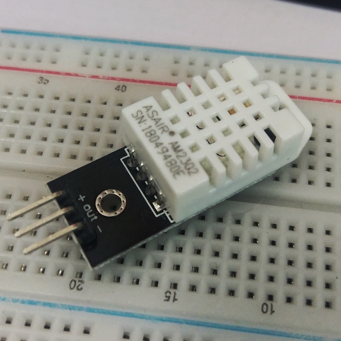
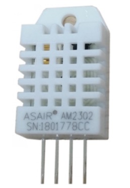
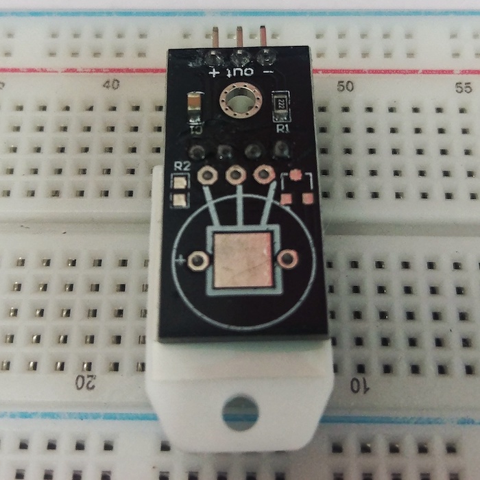
DHT22样子是这样。上面写着ASAIR AM2302,表示使用的奥松的AM2302型温湿度传感器。每次使用一个设备之前都必须要了解这个设备的信息,奥松官网有详细的AM2303手册参考。
AM2302
在奥松官网上的AM2302是4个针脚(如下图)。和我们买的有些不一样,淘宝上4PIN和3PIN的都有卖,区别在于3PIN的在数据接口整合的一个上拉电阻,这样在一些开发板上使用时就不需要自己接上拉电阻了。而对于树莓派来说GPIO都有上拉电阻,所以理论上来说使用4针的也可以不外接上拉电阻。
参数
| 供电电压 | DC:3.3-5.5V |
| 测量范围(温度) | -40~+80℃ |
| 测量范围(湿度) | 0~99%RH |
| 温度精度 | ±0.5℃(25℃环境下) |
| 湿度精度 | ±2%RH(25℃环境下) |
| 分辨率 | 温度:0.1℃ 湿度:0.1%RH |
| 衰减值(温度) | <0.1℃/年 |
| 衰减值(湿度) | <0.5%RH/年 |
| 传感器 | 电容式湿度传感器 |
| 输出信号 | 单总线数字信号 |
| 外壳材料 | PC塑料 |
上表是AM2302的基本参数,温度范围是-40~+80,在东北也基本够用了。使用的是电容湿度传感器和电阻温度传感器。
- 测湿度原理:湿敏电容一般是用高分子薄膜电容制成的,常用的高分子材料有聚苯乙烯、聚酰亚胺、酪酸醋酸纤维等。当环境湿度发生改变时,湿敏电容的介电常数发生变化,使其电容量也发生变化,其电容变化量与相对湿度成正比。。
- 测温度原理:热敏电阻值随着温度的增加线性增加或者降低。根据曲线换算出温度。
接口
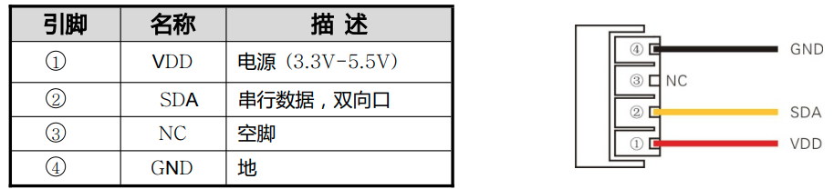
AM2302是有4个针脚,定义如上,其中PIN3为空。所以封装之后一般只提供3个针脚。二号针口是SDA数据总线,AM2302使用的是单总线协议进行通信。电压是3.3V-5V,所以对于树莓派来说可以直接使用3.3V驱动,但是官网建议使用5V驱动。 使用5V要注意一个问题, SDA输出数据给树莓派时高电平是5V,这个可能会损坏树莓派,所以需要把5V降到3.3V。 建议使用3.3V电压时连线长度不能超过1米。
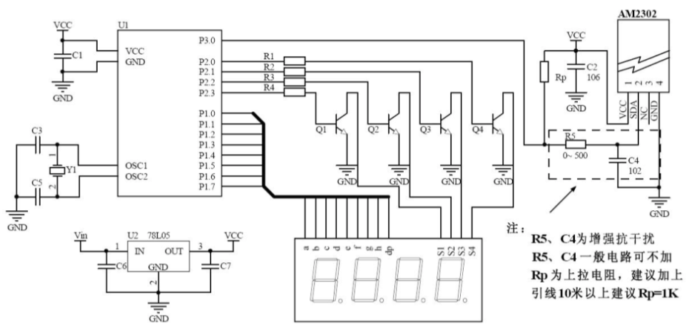
上面是官方文档给出的一个典型连线方式,左边是开发板和其他外设。右上是AM2302,周围有一些电路。虚线框的R5和C4是用来防干扰的,一般可以不叫。而左边Rp是用来作为上拉电阻。所以淘宝上买的3针的就是封装了上拉电阻和电容。从电路板被扣可以看到有C1和R1。
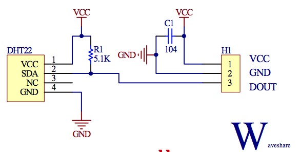
正好在网上也找到了3针DHT22的电路图, H1是对外的接口,看到SDA和DOUT之间有一个5.1K的上拉电阻。不同封装这个电阻值可能是不一样的。奥松文档建议是当连线小于30米时使用5.1K上拉电阻,大于30米时根据情况降低上拉电阻。 使用上拉电阻的目的是当总线闲置时,其状态为高电平。
协议
DHT22采用单总线通信协议。 树莓派和DHT22之间是主从结构,只有主机呼叫传感器,传感器才会应答,所以主机必须严格准守单总线的时序,如果时序混乱,传感器不会应答。传感器一次应答40位数据。传感器应答完成后进入休眠,等待下一次请求。
|
名称 |
单总线格式定义 |
|
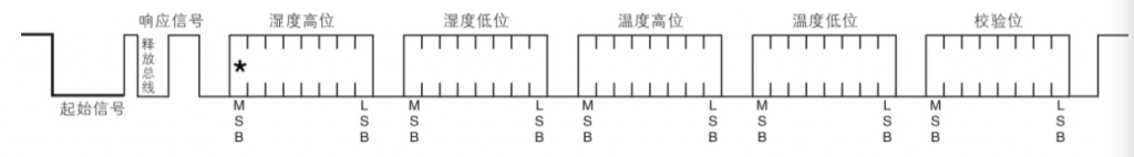
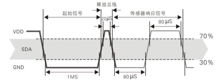
起始信号 |
微处理器把数据总线(SDA)拉低一段时间(至少 800μ s)[1],通知传感器准备数据。 |
|
响应信号 |
传感器把数据总线(SDA)拉低 80μ s,再接高 80μ s 以响应主机的起始信号。 |
|
数据格式 |
收到主机起始信号后,传感器一次性从数据总线(SDA)串出 40 位数据,高位先 出。 |
|
湿度 |
湿度分辨率是 16Bit,高位在前;传感器串出的湿度值是实际湿度值的 10 倍。 |
|
温度 |
温度分辨率是 16Bit,高位在前;传感器串出的温度值是实际温度值的 10 倍;温 度最高位(Bit15)等于 1 表示负温度,温度最高位(Bit15)等于 0 表示正温度; 温度除了最高位(Bit14~Bit0)表示温度值。 |
|
校验位 |
校验位=湿度高位+湿度低位+温度高位+温度低位。 |
读取流程
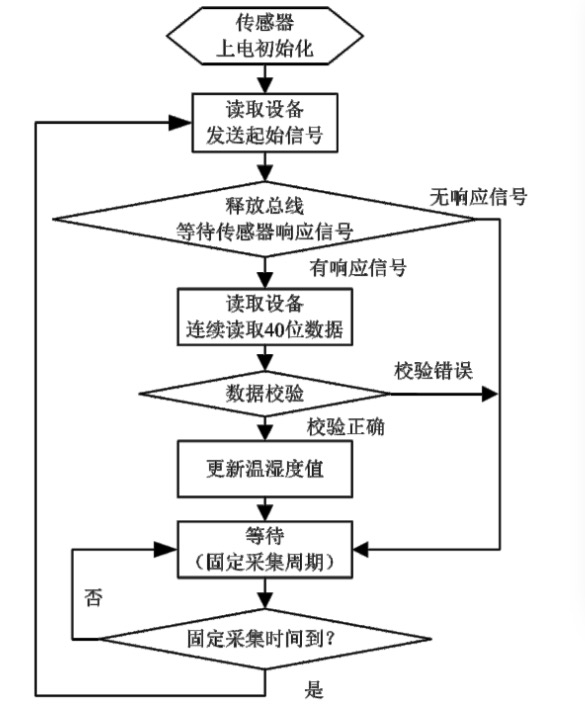
- 传感器上电之后2S的不稳定期内主机不能发送指令
- 每次发指令读取的是上一次的数据,如果要读取最新数据要读取2次
- 每次读取最低间隔是2S
整体来说整个协议还是比较简单,文档上有更详细的时序描述和如何从40位数据中获取温度和湿度。
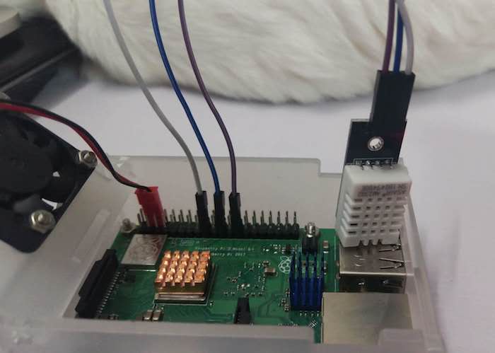
二 线路连接
为了不外接5V到3.3V的降压电路,我先用3.3V供电。数据线连接任意一个GPIO口都可以。 最终选择了如下接口:
- BOARD 17: 3.3V
- BOARD 21: GPIO9
- BOARD 25: GND
三 读取温度
虽然前面大概了解了AM2302的数据协议,但是自己写的话还是的花很多时间,所以从网上找一下DHT22相关的代码。Github上有DHT系列的python库:Adafruit Python DHT Sensor Library
Python library to read the DHT series of humidity and temperature sensors on a Raspberry Pi or Beaglebone Black.
Designed specifically to work with the Adafruit DHT series sensors —-> https://www.adafruit.com/products/385
Currently the library is tested with Python 2.6, 2.7, 3.3 and 3.4. It should work with Python greater than 3.4, too.
一种方式是通过pip直接安装, 如果使用pyhton3,需要使用pip3安装。
sudo pip install Adafruit_DHT

Collecting Adafruit_DHT
  Downloading https://files.pythonhosted.org/packages/7f/04/faf8ffa98f2ad8a8fe0f87ffa64690460f6f95a30a25385ea0a95263bf56/Adafruit_DHT-1.3.4.tar.gz
Building wheels for collected packages: Adafruit-DHT
  Running setup.py bdist_wheel for Adafruit-DHT ... done
  Stored in directory: /root/.cache/pip/wheels/f8/ef/98/ff02c0b8eabc91f4d6f79fc30e4c86cc76cd4c1c9d9f2d3cb1
Successfully built Adafruit-DHT
Installing collected packages: Adafruit-DHT
Successfully installed Adafruit-DHT-1.3.4
一种是下载源码,自己编译安装,
git clone https://github.com/adafruit/Adafruit_Python_DHT.git安装
cd Adafruit_Python_DHT
sudo python setup.py install
源码中有一个Sample,AdafruitDHT.py, 参数是DHT型号以及数据的GPIO号, 我们是DHT22,GPIO9,所以参数是22和9
cd Adafruit_Python_DHT/examples
./AdafruitDHT.py 22 9
Temp=29.2*  Humidity=75.4%
执行后从传传感器读取了温度和湿度。说明连线和程序都OK了, 3.3V是可以正常工作的。 湿度这么高啊。。单反防潮箱要买起来了。
四 源码简析
这么快就搞定了,一行代码都没写,作为一个码农完全不能忍。所以老规矩,看看源码。
# Parse command line parameters.
sensor_args = { '11': Adafruit_DHT.DHT11,
                '22': Adafruit_DHT.DHT22,
                '2302': Adafruit_DHT.AM2302 }
if len(sys.argv) == 3 and sys.argv[1] in sensor_args:
    sensor = sensor_args[sys.argv[1]]
    pin = sys.argv[2]
else:
    print('Usage: sudo ./Adafruit_DHT.py [11|22|2302] <GPIO pin number>')
    print('Example: sudo ./Adafruit_DHT.py 2302 4 - Read from an AM2302 connected to GPIO pin #4')
    sys.exit(1)

# Try to grab a sensor reading.  Use the read_retry method which will retry up
# to 15 times to get a sensor reading (waiting 2 seconds between each retry).
humidity, temperature = Adafruit_DHT.read_retry(sensor, pin)

# Un-comment the line below to convert the temperature to Fahrenheit.
# temperature = temperature * 9/5.0 + 32

# Note that sometimes you won't get a reading and
# the results will be null (because Linux can't
# guarantee the timing of calls to read the sensor).
# If this happens try again!
if humidity is not None and temperature is not None:
    print('Temp={0:0.1f}*  Humidity={1:0.1f}%'.format(temperature, humidity))
else:
    print('Failed to get reading. Try again!')
    sys.exit(1)
Sample很简单,调用了Adafruit_DHT库的read_retry接口来获取温度和湿度。有一点就是设备有DH11\DH22\AM2302,不清楚DH22和AM2302有什么区别,反正2个都可以正确获取到数据。
Adafruit_DHT Library
下载下来的整个源码如下, 这个库支持Raspberry和Beaglebone Black。 这个库从时间上来看已经有4年多了,他并没有使用前面我们使用的RPi.GPIO或wiringPi来作为操作GPIO的底层库,而是自己用C写的, 这一部分代码都在source目录下,算是DHT设备的驱动。 而Adafruit_DHT 目录是用python写的接口,用调用了DHT的C库驱动来提供给其他python用。
.
├── Adafruit_DHT
│   ├── Beaglebone_Black.py
│   ├── common.py
│   ├── __init__.py
│   ├── platform_detect.py
│   ├── Raspberry_Pi_2.py
│   ├── Raspberry_Pi.py
│   └── Test.py
├── examples
│   ├── AdafruitDHT.py
│   ├── google_spreadsheet.py
│   └── simpletest.py
├── LICENSE
├── MANIFEST.in
├── README.md
├── setup.py
└── source
    ├── Beaglebone_Black
    │   ├── bbb_dht_read.c
    │   ├── bbb_dht_read.h
    │   ├── bbb_mmio.c
    │   └── bbb_mmio.h
    ├── _Beaglebone_Black_Driver.c
    ├── common_dht_read.c
    ├── common_dht_read.h
    ├── Raspberry_Pi
    │   ├── pi_dht_read.c
    │   ├── pi_dht_read.h
    │   ├── pi_mmio.c
    │   └── pi_mmio.h
    ├── Raspberry_Pi_2
    │   ├── pi_2_dht_read.c
    │   ├── pi_2_dht_read.h
    │   ├── pi_2_mmio.c
    │   └── pi_2_mmio.h
    ├── _Raspberry_Pi_2_Driver.c
    ├── _Raspberry_Pi_Driver.c
    ├── Test
    │   ├── test_dht_read.c
    │   └── test_dht_read.h
    └── _Test_Driver.c
Python库源码
从上而下,先看看Python库的内容。
__Init__.py
from .common import DHT11, DHT22, AM2302, read, read_retry很简单,从common模块引入了DH11、DH22、AM2302属性,然后是read和read_retry方法。 这些实现都在common.py文件中
import time

from . import platform_detect


# Define error constants.
DHT_SUCCESS        =  0
DHT_ERROR_TIMEOUT  = -1
DHT_ERROR_CHECKSUM = -2
DHT_ERROR_ARGUMENT = -3
DHT_ERROR_GPIO     = -4
TRANSIENT_ERRORS = [DHT_ERROR_CHECKSUM, DHT_ERROR_TIMEOUT]

# Define sensor type constants.
DHT11  = 11
DHT22  = 22
AM2302 = 22
SENSORS = [DHT11, DHT22, AM2302]


def get_platform():
    """Return a DHT platform interface for the currently detected platform."""
    plat = platform_detect.platform_detect()
    if plat == platform_detect.RASPBERRY_PI:
        # Check for version 1 or 2 of the pi.
        version = platform_detect.pi_version()
        if version == 1:
            from . import Raspberry_Pi
            return Raspberry_Pi
        elif version == 2:
            from . import Raspberry_Pi_2
            return Raspberry_Pi_2
        elif version == 3:
            """Use Pi 2 driver even though running on Pi 3"""
            from . import Raspberry_Pi_2
            return Raspberry_Pi_2
        else:
            raise RuntimeError('No driver for detected Raspberry Pi version available!')
    elif plat == platform_detect.BEAGLEBONE_BLACK:
        from . import Beaglebone_Black
        return Beaglebone_Black
    else:
        raise RuntimeError('Unknown platform.')

def read(sensor, pin, platform=None):
    if sensor not in SENSORS:
        raise ValueError('Expected DHT11, DHT22, or AM2302 sensor value.')
    if platform is None:
        platform = get_platform()
    return platform.read(sensor, pin)

def read_retry(sensor, pin, retries=15, delay_seconds=2, platform=None):
    for i in range(retries):
        humidity, temperature = read(sensor, pin, platform)
        if humidity is not None and temperature is not None:
            return (humidity, temperature)
        time.sleep(delay_seconds)
    return (None, None)
关键的方法是read方法,参数是传感器类型、GPIO针脚。Sample中调用的read_retry 只是封装了一下重试次数和间隔时间。
read方法通过get_platform获取当前平台对象,然后调用平台对应的read方法读取温度和湿度。其中platform_detect 里面是通过读取/proc/cpu来判断平台的,比较简单,源码就不贴了。可以看到树莓派3和2使用的是相同的驱动。 引入Raspberry_Pi_2 类。
Raspberry_Pi_2.py
from . import common
from . import Raspberry_Pi_2_Driver as driver

def read(sensor, pin):
    # Validate pin is a valid GPIO.
    if pin is None or int(pin) < 0 or int(pin) > 31:
        raise ValueError('Pin must be a valid GPIO number 0 to 31.')
    # Get a reading from C driver code.
    result, humidity, temp = driver.read(sensor, int(pin))
    if result in common.TRANSIENT_ERRORS:
        # Signal no result could be obtained, but the caller can retry.
        return (None, None)
    elif result == common.DHT_ERROR_GPIO:
        raise RuntimeError('Error accessing GPIO.')
    elif result != common.DHT_SUCCESS:
        # Some kind of error occured.
        raise RuntimeError('Error calling DHT test driver read: {0}'.format(result))
return (humidity, temp)这是树莓派2,3平台对用的read的实现,直接调用的Raspberry_Pi_2_Driver 模块的read方法。这个模块就是C库的代码。 所以整个Python层的代码非常简单。
C库Driver源码
对于C暴露模块给Python没弄过不懂,所以在网上搜索了下。一个典型的Python扩展模块至少应该包含三个部分:导出函数、方法列表和初始化函数。
Raspberry_Pi_2_Driver.c
这个是C语言的暴露给Python的树莓派模块。具体看一下代码。 下面就是方法列表, 有点象JNI,python的read方法对应着C的Raspberry_Pi_2_Driver_read 方法。
static PyMethodDef module_methods[] = {
    {"read", Raspberry_Pi_2_Driver_read, METH_VARARGS, "Read DHT sensor value on a Raspberry Pi 2."},
    {NULL, NULL, 0, NULL}
};
在看看初始化函数,定义了Python模块的名字,方法列表。然后对模块进行初始化。 这里吃吃python2和python3
#if PY_MAJOR_VERSION > 2
static struct PyModuleDef pi2_dht_module = {
    PyModuleDef_HEAD_INIT,
    "Raspberry_Pi_2_Driver",   // name of module
    NULL,                      // module documentation, may be NULL
    -1,                        // size of per-interpreter state of the module, or -1 if the module keeps state in global variables.
    module_methods
};
#endif

#if PY_MAJOR_VERSION > 2
PyMODINIT_FUNC PyInit_Raspberry_Pi_2_Driver(void)
#else
PyMODINIT_FUNC initRaspberry_Pi_2_Driver(void)
#endif
{
    #if PY_MAJOR_VERSION > 2
      PyObject* module = PyModule_Create(&pi2_dht_module);
    #else
      Py_InitModule("Raspberry_Pi_2_Driver", module_methods);
    #endif

    #if PY_MAJOR_VERSION > 2
       return module;
    #else
       return;
    #endif
}
最后就是关键的read方法的C层的实现, 调用的是pi_2_dht_read 方法,参数就是python传入的传感器和GPIO针脚号。方法定义在 pi_2_dht_read.h
// Wrap calling dht_read function and expose it as a DHT.read Python module & function.
static PyObject* Raspberry_Pi_2_Driver_read(PyObject *self, PyObject *args)
{
	// Parse sensor and pin integer arguments.
    int sensor, pin;
    if (!PyArg_ParseTuple(args, "ii", &sensor, &pin)) {
        return NULL;
    }
    // Call dht_read and return result code, humidity, and temperature.
    float humidity = 0, temperature = 0;
    int result = pi_2_dht_read(sensor, pin, &humidity, &temperature);
    return Py_BuildValue("iff", result, humidity, temperature);
}
看看pi_2_dht_read具体实现。 首先是初始化
- 设置GPIO口为输出
- GPIO设置为高电平 500ms (初始状态)
- GPIO设置为低电平 20ms (向设备发起起始信号)
- 设置GPIO口为输入 (因为上拉电阻,输入为高电平)
- 传感器收到请求后,会发送80us的低电平作为应答,所以这里用for循环等待一会
- 然后传感器发送80us的高电平通知树莓派准备接受,用while循环检查是否收到高电平
 // Initialize GPIO library.
  if (pi_2_mmio_init() < 0) {
    return DHT_ERROR_GPIO;
  }

  // Store the count that each DHT bit pulse is low and high.
  // Make sure array is initialized to start at zero.
  int pulseCounts[DHT_PULSES*2] = {0};

  // Set pin to output.
  pi_2_mmio_set_output(pin);

  // Set pin high for ~500 milliseconds.
  pi_2_mmio_set_high(pin);
  sleep_milliseconds(500);

  // The next calls are timing critical and care should be taken
  // to ensure no unnecssary work is done below.

  // Set pin low for ~20 milliseconds.
  pi_2_mmio_set_low(pin);
  busy_wait_milliseconds(20);

  // Set pin at input.
  pi_2_mmio_set_input(pin);
  // Need a very short delay before reading pins or else value is sometimes still low.
  for (volatile int i = 0; i < 50; ++i) {
  }

  // Wait for DHT to pull pin low.
  uint32_t count = 0;
  while (pi_2_mmio_input(pin)) {
    if (++count >= DHT_MAXCOUNT) {
      // Timeout waiting for response.
      set_default_priority();
      return DHT_ERROR_TIMEOUT;
    }
  }
这个时候树莓派就可以从传感器读取40位的数据了。
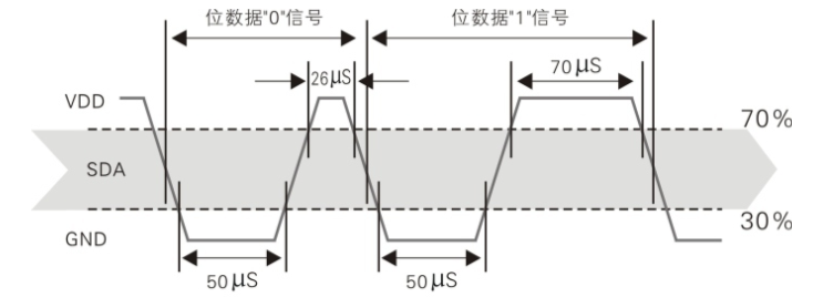
- 数据0:50us低电平+26-28us高电平
- 数据1:50us低电平+70us的高电平
所以1个数据是有2个脉冲信号,所以在读取数据时是DHT_PULSES*2。 这里是通过脉冲信号宽度来区分是0 还是1,所以很巧妙利用while循环每次加1计数,所以pulseCounts数组里面的值是脉冲的宽度,整个数组就是收到的40bit数据的脉冲信号序列。 (让我来写我估计想不出怎么区分脉冲宽度。。)
  // Record pulse widths for the expected result bits.
  for (int i=0; i < DHT_PULSES*2; i+=2) {
    // Count how long pin is low and store in pulseCounts[i]
    while (!pi_2_mmio_input(pin)) {
      if (++pulseCounts[i] >= DHT_MAXCOUNT) {
        // Timeout waiting for response.
        set_default_priority();
        return DHT_ERROR_TIMEOUT;
      }
    }
    // Count how long pin is high and store in pulseCounts[i+1]
    while (pi_2_mmio_input(pin)) {
      if (++pulseCounts[i+1] >= DHT_MAXCOUNT) {
        // Timeout waiting for response.
        set_default_priority();
        return DHT_ERROR_TIMEOUT;
      }
    }
  }
后面就是对这个脉冲宽度序列进行分析了,因为树莓派并不是实时系统,所以前面使用循环计数会有点问题,就是低电平50us每次循环的次数可能不一样,所以这里先把所有低电平50us的个数相加并取了平均值,这个值代表50us
  // Compute the average low pulse width to use as a 50 microsecond reference threshold.
  // Ignore the first two readings because they are a constant 80 microsecond pulse.
  uint32_t threshold = 0;
  for (int i=2; i < DHT_PULSES*2; i+=2) {
    threshold += pulseCounts[i];
  }
threshold /= DHT_PULSES-1;那么比这个threshold值大的高电平就是数值1,而小于这个值的高电平就是0, 因为分别是26us和70us,所有有一定的容错率。当然如果发生线程切换之类无法保证时序就会导致出现大的误差,所有有时候会获取到结果,所以在python层retry_read才有了一个重读的机制, 此方法有对应的注释如下。
Note that because the sensor requires strict timing to read and Linux is not a real time OS, a result is not guaranteed to be returned! In some cases this will return the tuple (None, None) which indicates the function should be retried.
关于实时系统可以网上搜一下,主要就是:实时操作系统计算的正确性不仅取决于计算逻辑的正确性取决于产生结果的时间。下面代码就很简单了,和threshold 比较,得到真正的40bit数据,存入到5个字节的data数组中。
// Interpret each high pulse as a 0 or 1 by comparing it to the 50us reference.
  // If the count is less than 50us it must be a ~28us 0 pulse, and if it's higher
  // then it must be a ~70us 1 pulse.
  uint8_t data[5] = {0};
  for (int i=3; i < DHT_PULSES*2; i+=2) {
    int index = (i-3)/16;
    data[index] <<= 1;
    if (pulseCounts[i] >= threshold) {
      // One bit for long pulse.
      data[index] |= 1;
    }
    // Else zero bit for short pulse.
  }
获取到data数组中
- 湿度:data[0]和data[1]
- 温度:data[2]和data[3]
- 检验位:data[4]
验证很简答,验证为应该是前面4位或运算的结果。 验证成功的话计算出温度和湿度。 其中温度为负数时最高位是1。
// Verify checksum of received data.
  if (data[4] == ((data[0] + data[1] + data[2] + data[3]) & 0xFF)) {
    if (type == DHT11) {
      // Get humidity and temp for DHT11 sensor.
      *humidity = (float)data[0];
      *temperature = (float)data[2];
    }
    else if (type == DHT22) {
      // Calculate humidity and temp for DHT22 sensor.
      *humidity = (data[0] * 256 + data[1]) / 10.0f;
      *temperature = ((data[2] & 0x7F) * 256 + data[3]) / 10.0f;
      if (data[2] & 0x80) {
        *temperature *= -1.0f;
      }
    }
    return DHT_SUCCESS;
  }
  else {
    return DHT_ERROR_CHECKSUM;
  }
}
真个逻辑不复杂,但是脉冲那一段还是很巧妙的。
GPIO操作
理解了上面的逻辑,我们自己很容易用PRi.GPIO的pyhton库来重写一边这个逻辑。 但是这里使用的是一个自己实现的mmio库。介绍是:
Simple fast memory-mapped GPIO library for the Raspberry Pi.
int fd = open("/dev/gpiomem", O_RDWR | O_SYNC);
    if (fd == -1) {
      // Error opening /dev/gpiomem.
      return MMIO_ERROR_DEVMEM;
    }
    // Map GPIO memory to location in process space.
    pi_2_mmio_gpio = (uint32_t*)mmap(NULL, GPIO_LENGTH, PROT_READ | PROT_WRITE, MAP_SHARED, fd, gpio_base);
    close(fd);
之前看了下PRi.GPIO的C库实现,其实都差不多,Linux本身是有gpio驱动的,所以代码和GPIO通信实际也是使用linux的gpio驱动。 一般驱动都会搞一个块设备,这样既可以通过读写这个设备来和驱动交互达到控制GPIO的目录,这里一样,通过mmap内存映射/dev/gpiomem,然后操作GPIO端口, 看看pi_2_mmio.h头文件中就知道了,在具体为什么这样操作就和GPIO驱动有关了,这个就过于深入了。
extern volatile uint32_t* pi_2_mmio_gpio;

static inline void pi_2_mmio_set_input(const int gpio_number) {
  // Set GPIO register to 000 for specified GPIO number.
  *(pi_2_mmio_gpio+((gpio_number)/10)) &= ~(7<<(((gpio_number)%10)*3));
}

static inline void pi_2_mmio_set_output(const int gpio_number) {
  // First set to 000 using input function.
  pi_2_mmio_set_input(gpio_number);
  // Next set bit 0 to 1 to set output.
  *(pi_2_mmio_gpio+((gpio_number)/10)) |=  (1<<(((gpio_number)%10)*3));
}

static inline void pi_2_mmio_set_high(const int gpio_number) {
  *(pi_2_mmio_gpio+7) = 1 << gpio_number;
}

static inline void pi_2_mmio_set_low(const int gpio_number) {
  *(pi_2_mmio_gpio+10) = 1 << gpio_number;
}

static inline uint32_t pi_2_mmio_input(const int gpio_number) {
  return *(pi_2_mmio_gpio+13) & (1 << gpio_number);
}
后面有机会也会了解下GPIO低层实现, 这里代码一共才几十行,怎么PRi.GPIO的C库好像很多代码的样子。有时间尝试直接用PRi.GPIO库直接实现python代码。


写的很好啊,博主为什么不传到Github上,好Fork一下